5.3. Transport Layer
Up to this point, we have used application-layer socket programming essentially as another form of IPC for exchanging data between processes on different hosts. Communication at that level can follow a protocol that defines human-readable message formats, such as HTTP. Other applications, such as DNS or DHCP, exchange highly structured binary messages that are intended to be interpreted by peer processes. In either regard, the communication is specific to that application, and there is an assumption that “the network”—a mysterious, almost magical entity—transmits the data. That is, application-layer network programming can be easily conflated with other forms of IPC, replacing the OS with the network as the service provider. There is truth to this conflation, as some layers and protocols (including TCP and IP) are typically implemented within the OS. However, other layers are implemented in hardware, including network interface cards, cables between devices, and radios.
The transport layer provides the first level of abstraction that application-layer
programmers rely on. Specifically, the transport layer establishes the logical structure of a
virtual end-to-end communication channel between processes. When you use a web browser to
access www.example.com, you are intending to communicate with a particular process running on
that other host, not just the machine in general; you would probably be surprised if your web
browser suddenly began showing you binary DHCP or DNS responses instead of HTML-formatted
information. The transport layer ensures that your request gets delivered to the process running the
web server on the remote host, while returning the web page to your web browser process.
In contrast to a monolithic entity like an OS, the network is a layered architecture of distributed components that cooperate to exchange data. For a variety of reasons, the distributed nature of these components causes failed attempts at a significantly higher rate than an OS would ever encounter. As an example, consider the effect of someone tripping over the cord of a server and unplugging it; there is no possible way for your laptop to communicate with another machine that is turned off. As a less extreme example, the message might not actually be lost, but it may encounter a delay in the network that causes it to arrive too late. Failures and disruptions like this can happen at any time. One key feature for choosing a transport layer protocol is whether or not the application is requesting a reliable transport service that attempts to correct failures that occur. UDP provides fast but unreliable transport, while TCP features reliable transport.
5.3.1. Unreliable Transport: UDP
The simpler approach to transport-layer service is to provide an unreliable transport, which is the purpose of the User Datagram Protocol (UDP), defined in RFC 768. UDP provides a fast best effort delivery service, which is a polite way to say that it will try but it makes no guarantees. UDP provides a minimal amount of end-to-end error checking to determine if the full payload has been received and the contents have not been corrupted during transmission.
| 0-15 | 16-31 |
|---|---|
source port |
destination port |
length |
checksum |
payload(application-layer data) |
|
Table 5.2: Structure of a UDP segment
Table 5.2 shows the structure of a UDP segment. The datagram contains a header with four fields: the port numbers of the source and destination processes, the length of the segment (including both the header and the payload), and a 16-bit checksum calculation. The following examples show the UDP segment for a DNS request from the previous chapter.

Example 5.3.1
In this example, the client had opened ephemeral port 5000 (0x1388) and sent the request to the
OpenDNS server, which was listening on port 53 (0x0035). The header requires eight bytes and the
request payload was 29 bytes, so the total length of the UDP segment was 37 bytes; the response was
53 bytes, due to the longer response in the payload.
| Header | 1388 |
source port = 5000 (0x1388) |
| Payload | 1234 0100 0001 0000 0000 0000 |
DNS request for example.com |
| Header | 0035 |
source port = 53 (0x0035) |
| Payload | 1234 8180 0001 0001 0000 0000 |
DNS response for example.com |
The checksum value is the result of repeated one’s complement addition of 16-bit values in the
UDP segment, as shown in Code Listing 5.1. In UDP, the checksum is evaluated over the
payload, parts of the IP header (which we are ignoring here, as we have not examined IP yet), and a
UDP pseudo-header. The UDP pseudo-header contains the source port, destination port,
and the length fields of the regular UDP header. The checksum field is replaced with a
16-bit value containing information about the protocol, which is defined in RFC 762; for UDP, this
16-bit value is 0x0011. Regarding the payload, if there are an odd number of bytes (as shown in the
previous messages), that last byte is concatenated with zeroes to create a 16-bit value.
1 2 3 4 5 6 7 8 9 10 11 12 13 14 15 16 17 18 19 20 21 22 23 24 25 26 27 | /* Code Listing 5.1:
Calculate a 16-bit checksum for use in UDP
*/
/* Calculates a 16-bit checksum */
uint16_t
cksum (uint16_t *bytes, size_t length)
{
uint32_t sum = 0;
/* Loop through, adding 16 bits at a time */
for (size_t i = 0; i < length / 2; i++)
{
sum += bytes[i];
/* If there is a leading 1, combine the two halves */
if (sum & 0x80000000)
sum = (sum & 0xffff) + (sum >> 16);
}
/* If there are an odd number of bytes, pad the last with leading
zeroes */
if ( (length % 2) == 1)
sum += ((uint8_t *)bytes)[length - 1];
/* Finalize the result by combining the two halves and flipping
the bits */
sum = (uint16_t) sum + (uint16_t) (sum >> 16);
return ~sum;
}
|
Table 5.3 illustrates the mechanics of how one’s complement addition works by adding the
values 0x7d09 and 0xb5fc. The result of this calculation would be 0x13305 based on
binary arithmetic that does not require a fixed size. However, UDP checksums are fixed at a length
of 16 bits. Whenever the addition would produce a carry out of 1 (requiring a 17th bit),
that bit is folded around to the least-significant bit location. Consequently, the leading bit of
0x13305 would be removed (creating 0x3305) and added to the least-significant bit, yielding
the result 0x3306.
7d09 |
0 1 1 1 |
1 1 0 1 |
0 0 0 0 |
1 0 0 1 |
|
b5fc |
1 0 1 1 |
0 1 0 1 |
1 1 1 1 |
1 1 0 0 |
|
13305 |
1 |
0 0 1 1 |
0 0 1 1 |
0 0 0 0 |
0 1 0 1 |
3306 |
0 0 1 1 |
0 0 1 1 |
0 0 0 0 |
0 1 1 0 |
UDP checksum for two 16-bit values
The UDP checksum provides a minimal form of error-checking for end-to-end communication. As we will note later in this chapter, both IP and Ethernet also provide error detection. As such, if the segment is sent with these network and link layer protocols, UDP is performing a redundant service. Furthermore, as UDP will make no attempt to correct the errors it detects, the UDP checksum may seem to be pointless redundancy. This criticism is fair, although UDP can also be used with other network or link-layer protocols that do not perform error correction. One disadvantage of a layered architecture, such as the Internet protocol stack, is that the individual layers must be designed without underlying assumptions of the other layers.
At first glance, UDP’s unreliable transport service may appear to be a poor choice, and for certain
applications it is. But UDP provides service that is good enough for other applications, while
avoiding the overhead penalties associated with a reliable transport. For instance, UDP is commonly
used in streaming multimedia applications that only require most of the data to be successfully
transmitted; the application can compensate for lost data by providing slightly worse quality, such
as pixelated images or temporarily pausing the media until more data can be received and buffered.
The application can detect the lost or corrupted data by checking the return value from
recvfrom(), sending new requests only as needed. UDP is also commonly used in application-layer
services that users do not typically interact with directly, such as DNS or DHCP.
5.3.2. Reliable Transport: TCP
Although UDP provides a lightweight, fast transport service, the unreliability is simply not appropriate for some applications. Consider how frustrating it would be to visit a web page that was missing a portion of text; if the missing data occurred in the middle of HTML formatting or link tags, then the appearance would be wrong or links to other web pages would be broken. As such, many applications require the reliable transport service provided by the Transmission Control Protocol (TCP), which is defined primarily in RFC 793. TCP is a connection-oriented protocol, indicating that the hosts maintain some form of state between messages. That is, the hosts create a connection to establish a session that is likely to contain multiple messages sent back and forth between the hosts; during this session, hosts may resend messages that are lost or corrupted, while also taking steps to avoid overwhelming each other with too much data at any time. The full operation of TCP is rather complex, but we will restrict our focus to the key concepts of reliable data delivery and flow control.
As with UDP, TCP segments include the 16-bit source and destination port numbers to designate the
processes at either end of the connection, as shown in Table 5.4. Similarly, the TCP
header contains a checksum that is used to detect errors that may have occurred in transmission; in
contrast to UDP, the TCP pseudo-header is based on information from the IP header. The urgent data
pointer is not used in modern practice, and the optional fields are beyond the scope of this book.
The other fields are explained below to illustrate the functioning of TCP reliable transport and flow control.
| 0-7 | 8-15 | 16-23 | 24-31 |
|---|---|---|---|
source port |
destination port |
||
sequence number (SEQ) |
|||
acknowledgement number (ACK) |
|||
flags |
receive window |
||
checksum |
urgent data ptr |
||
optional fields |
|||
payload(application-layer data) |
|||
Table 5.4: Structure of a TCP segment
In TCP segments, the sequence number (SEQ) is an identifier associated with the current
segment. Each host randomly chooses an initial value for the sequence number. Each time a host sends
a segment, it increments its internal counter for the sequence number by the size of the payload.
For example, consider a client application that uses SEQ=25 for a segment containing the five
bytes "Hello". If the client’s next segment is to sends the seven bytes "Goodbye", it would
use SEQ=30. As this segment contains seven bytes, the client’s next segment would use
SEQ=37. In short, the sequence number denotes the order and the size of the application-layer
payload data.
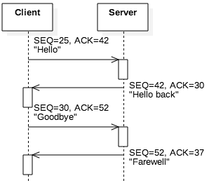
Figure 5.3.2: A TCP data exchange of four messages
At the other end, the acknowledgement number (ACK) allows a receiving host to inform the
sender that the segment was received. In the previous scenario, when the server receives the
client’s "Hello" segment (five bytes sent with SEQ=25), the server’s next segment would
contain the ACK=30 (SEQ + 5). Figure 5.3.2 shows the sample exchange that we
have been describing. The client’s first segment used SEQ=25; the client sent the ACK=42,
indicating that was the value it expected for the server’s next segment. (This ACK is based on
segments shown before this sequence.) The server then responds with a segment that does, in fact,
use SEQ=42. Since this segment ("Hello back") contains 10 bytes, the client indicates it
received the segment by using ACK=52 in its next segment.
During the session, the OS on each host maintains a buffer for storing data until the application reads it from the socket. As this buffer is finite in size, the hosts need to cooperate to prevent a buffer overflow. The receive window achieves this by declaring the maximum number of bytes that the sender is capable of receiving in the next segment. To observe how this value is used, consider the following analogous line of code when working with strings:
strncpy (buffer, input, sizeof (buffer));
The third parameter indicates the maximum number of bytes that will be copied into the buffer.
For instance, if the buffer has space for 20 bytes, but the input is a string that is 50
bytes in length, the third parameter prevents the additional 30 bytes from being written beyond the
end of the buffer. The receive window serves the same purpose within the context of TCP
segments. If the receiver’s next segment exceeds this size, then that host would need to break up
its response and send it across multiple segments. This cooperation is the TCP flow control
service, as each host takes steps to avoid sending too much data at a time.
There is subtle point regarding flow control that is easily misunderstood. Consider the sequence of
segments in Figure 5.3.2. In that scenario, the server sent two segments to the
client: one containing the string "Hello back" and one containing "Farewell". One possible
explanation is that the application issued two system calls to write to the socket. Flow control
provides another explanation. Although this string in particular is unlikely, the server application
may have written the string "Hello backFarewell" to the socket. The client’s first segment
(sequence number 25) may have included a receive window indicating it only had space for 10 bytes,
so the server’s TCP implementation split the segment. The key point is that TCP itself provides
flow, and the application is typically not made aware it is happening. The sender splits the segment
without informing the application, and the receiving host’s TCP implementation concatenates all
segments in its internal buffers as needed.
Example 5.3.2
The example shown here illustrates the full TCP header and payload for an HTTP GET request sent to example.com. The destination port number is 80, which is the well-known port number for HTTP, whereas the source port is an ephemeral port number, generated by the client’s OS. The receive window indicates that the client is requesting a maximum of 4096 bytes in response. The flags field will be explained in the next discussion on the TCP handshake, and the urgent data pointer field is not used. The payload here contains the HTTP application-layer request.
| Header | 1388 |
source port = 5000 (0x1388) |
| Payload | 4745 5420 2f20 4854 5450 2f31 |
GET / HTTP/1 |
5.3.3. TCP Handshake and Connections
Unlike the connectionless UDP that allows applications to send and receive data at any time, TCP requires that the two hosts must first establish a connection to begin a communication session. That is, prior to exchanging application-layer data, the hosts must send and receive some initial segments to ensure both hosts know to expect the data exchange. At each end, this procedure involves allocating internal buffers and variables, such as those needed for flow control. Just as importantly, the hosts must also execute the TCP handshake, a lightweight initial protocol that allows the hosts to declare their initial sequence numbers, receive windows, and other values.
The TCP handshake is implemented by exchanging empty segments with particular bits set in the TCP
header. Specifically, recall from Table 5.4 that the TCP header contains a 16-bit
flags field. Table 5.5 shows the internal structure of this field for a normal TCP
segment. The data offset field denotes the length of the TCP header in terms of 32-bit words.
The standard header, which contains no optional fields, has a length of five words; that constitutes
the minimum value of this field. If optional fields are used, this value can increase to 15, which
declares that TCP headers can be no longer than 60 bytes. The remainder of this section describes
the use of the ACK, SYN, and FIN bits.
| Index | 0-3 | 4-9 | 10-15 | |||||||||||||
|---|---|---|---|---|---|---|---|---|---|---|---|---|---|---|---|---|
| Meaning | data offset |
unused | U |
A |
P |
R |
S |
F |
||||||||
| Value | 0 |
1 |
0 |
1 |
0 |
0 |
0 |
0 |
0 |
0 |
0 |
0 |
0 |
0 |
0 |
0 |
| Hex | 5 |
0 |
0 |
0 |
||||||||||||
Table 5.5: Structure of the 16-bit TCP flags field
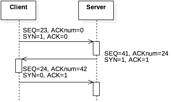
Figure 5.3.4: The TCP handshake
The TCP handshake is initiated by a client application that calls the connect() socket function
described in the previous chapter. The steps of the TCP handshake are shown in Figure 5.3.4 and consists of three segments, commonly referred to as "SYN",
"SYN-ACK", and "ACK" because of the bits they set. Note that this figure uses "ACKnum"
to refer to the 32-bit acknowledgement number and "ACK" to denote the bit in the 16-bit flags
field. A client initiates a TCP connection by sending a SYN segment ("synchronize") that
contains its randomly chosen SEQ value, setting SYN=1 and putting 0x5002 into the 16-bit
flags field. The server acknowledges receiving the synchronization request (setting SYN=1 and
ACK=1 to get 0x5012) and indicates its own initial sequence number. The client then responds
again with the ACK=1 (0x5010). Note that all of these segments use an empty payload, but the
sequence numbers are incremented as if they contained a single byte.
After completing the TCP handshake, the client and server share a logical connection. Both hosts
know each other’s sequence numbers and initial receive window sizes. The OS on both hosts has
established internal buffers, variables, and other data structures as needed. This internal state is
maintained until the two parties close the connection. To close the connection, one host sends a
segment with an empty payload and the finish bit FIN=1; the other host responds with an
ACK=1 segment. These two segments are then repeated, but with the other party sending the
FIN=1 segment. As such, either side can sever the connection at any time.

Note
A common misunderstanding is that the ACK bit is used only in the TCP handshake or the
FIN-ACK closing exchange. That is not correct. The ACK bit is set any time that the
acknowledgement number is significant. That is, any time that the sender intends for the receiver
to interpret this number as an acknowledgement of a previous message, the sender sets the ACK
bit.
Recall the distinction between HTTP/1.0 and HTTP/1.1 discussed in the previous chapter. HTTP
applications use TCP for their reliable transport layer. As such, any HTTP data exchange (such as
accessing a web page, as well as retrieving the needed images and script files, require an initial
TCP handshake to establish the connection. In HTTP/1.0, every object retrieved requires its own TCP
connection session; even if all of the objects are stored on the same server, the seven segments
(three for the handshake and four to close the connection) all must be performed, and both hosts’ OS
must repeated set up and destroy internal buffers and data structures. With HTTP/1.1, the TCP
handshake is only done once per server. The connection is maintained until the client application
sends a segment containing the HTTP header "Connection: close". The server and client then
exchange segments to close the connection.
Example 5.3.3
This example illustrates the flow of a TCP handshake to set up an HTTP request. As in Example 5.3.2, the source and destination port numbers consist of the well-know port 80 and
an ephemeral port. When the client (typically a web browser) establishes the connection, it starts
by picking a random sequence number (4973 in this case) and using 0 as the acknowledgement number.
The client sends an empty request (i.e., there is no payload and the message is just the TCP
header) to the server as a SYN request.
The server responds with a SYN-ACK that sets both of these bits in the flags field. (Observe
that the port numbers reverse in this middle message to indicate the direction switched to be
“server to client.”) As with the SYN request, the server selects a random initial sequence
number (627). The acknowledgement number here is the client’s sequence number incremented by 1
(4973 + 1). Finally, the client completes the handshake with an ACK message back to the server.
This ACK message uses the incremented sequence number (4974) and the incremented acknowledgement of
the server’s sequence number (628). At this point, the connection is established and both hosts
have established the sequence and acknowledgement numbers for future messages.
SYN request (client to server) |
1388 |
source port = 5000 (0x1388) |
SYN-ACK response (server to client) |
0050 |
source port = 80 (0x0050) |
ACK response (client to server) |
1388 |
source port = 5000 (0x1388) |
5.3.4. TCP Timeout and Packet Loss
The combination of the sequence number (SEQ) acknowledgement number (ACK) and the
checksum forms a rudimentary error detection scheme to support reliable transport. If a host
receives a segment with unexpected values in any of these fields, it can determine that something
has gone wrong in the data exchange. While the receiver may not be able to determine the exact cause
of the problem, the incorrect information can provide some guidance:
- Incorrect ACK: The sender may be indicating that the previous segment was corrupted or not received. For example, assume a client sends
"Hello"withSEQ=10; if the response containsACK=10, the"Hello"segment has not been acknowledged and should be re-sent.- Incorrect SEQ: A previous segment from the server may be delayed or lost, and the server is not aware of this fact. As an example, assume a client is expecting
SEQ=42based on a previous segment from the server. If the next segment it receives hasSEQ=52, then there is some data the client has not received. The missing data could be 10 one-byte segments or a single 10-byte segment; the client cannot know which is true and does not actually need to. Again, the client could re-send its last segment that containedACK=42, effectively refusing to acknowledge the newer data until the lost data is recovered.- Incorrect checksum: Some part of the TCP segment or the payload has been corrupted or removed in some way. As with the previous two cases, re-sending the last segment based on acknowledged data serves as a request for the server to repeat its own segment.
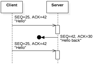
Figure 5.3.7: The client resends the message if the acknowledgement is lost
Figure 5.3.7 illustrates the notion of packet loss, another common scenario involving TCP reliability. In this case, the server received and acknowledge the client’s segment, but the client did not receive the server’s response. As a result, the client re-sent the segment as a second attempt. From an omniscient perspective of all network traffic, this segment seems unnecessary: We can observe that the server did, in fact, receive the segment the first time. However, such a perspective is impossible; hosts can only observe the segments they send and receive. From the client’s perspective, it is possible that the first segment—not the reply—was lost.
This simple scenario illustrates a critical design question for reliable transport: how long must the client want before declaring a packet lost? Hosts need to wait long enough for packets to traverse the network physically but waiting too long for a lost packet delays the recovery process. To complicate matters further, network conditions can change, so determining the optimal amount of time to wait is a moving target.
The original TCP specification in RFC 793 proposed measuring the round-trip time (RTT), which is the amount of time that elapses between sending a segment and receiving the response. As the host sends and receives additional segments, it computes a smoothed round-trip time (SRTT) as a rolling average of these delays. Based on an update in RFC 6298, in modern systems, the SRTT is initialized to the first RTT measurement. Once a new measurement (denoted as $R’$) is made, the SRTT is updated according to the following formula, with $\alpha$ typically set to 1/8.
Example 5.3.4
To illustrate this calculation, assume that the first measurement is $R = 4ms$. This value becomes the initial SRTT. The table below shows the changes that would occur if the next three segments arrive with updated $R’$ values of 10 ms, 20 ms, and 2 ms, in that order.Note that all time units get rounded based on the granularity of the clock, which is assumed to be 1 ms in this case.
| Old SRTT | $R'$ | Updated SRTT |
|---|---|---|
| 4 | 10 | (7/8) * 4 + (1/8) * 10 = 4.75 [rounded to 5] |
| 5 | 20 | (7/8) * 5 + (1/8) * 20 = 6.875 [rounded to 7] |
| 7 | 2 | (7/8) * 7 + (1/8) * 2 = 6.375 [rounded to 6] |
Table 5.6: SRTT calculations for a sequence of three received segments
The SRTT serves as an estimate for predicting the next RTT. The coefficients $\alpha$ and $(1 - \alpha)$ act as a relative weighting factor that influences how much the new observed value changes the estimate. Increasing the value of $\alpha$ places more weight on the most recent measurement, thus decreasing then influence of historical values. On the other hand, decreasing $\alpha$ has the opposite effect, relying more on the new RTT and less on the historical values.
The new SRTT value is used to update the retransmission timeout (RTO), which is the amount of time that the host will wait before declaring a lost packet. While RFC 793 proposed a formula for calculating RTO based just on SRTT, RFC 6298 updated this calculation. One problem with the original formulation is that it does not consider the impact of variance in RTT. For example, a system that repeatedly experiences an RTT of 20 ms every time should not be treated the same as one that alternates between 1 ms and 39 ms, despite both systems having the same average RTT. To compensate for this difference, RFC 6298 defines another rolling average, the RTT variation (RTTVAR), using $\beta = 1/4$:
To make sense of this factor, consider the role of the absolute value $| SRTT – R’ |$. This value denotes the difference between the predicted RTT (SRTT) and the RTT that was actually observed ($R’$). If the prediction was perfect every time, then this absolute value would be 0. Then, each new segment would shrink the RTTVAR to become 3/4 of its previous value. However, if there is great variance from segment to segment, then this absolute value will be positive, potentially increasing RTTVAR. As before, $\beta$ acts as a weighting factor to determine how much influence the new variation should have compared with the historical values.
Example 5.3.5
When calculating the new RTTVAR, the SRTT value used should be the old SRTT, not the updated value from Example 5.3.4. The initial RTTVAR is set to $R/2$ when there are no previous measurements to use. Since the example above used $R = 4$ as the initially observed RTT, RTTVAR is initialized to 2. The table below illustrates the calculations for RTTVAR for the sequence of observations $R’$ from before, using the standard value of $\beta = 1/4$.
| SRTT | $R'$ | Old RTTVAR | Updated RTTVAR |
|---|---|---|---|
| 4 | 10 | 2 | (3/4) * 2 + (1/4) * | 4 – 10 | = 3 |
| 5 | 20 | 3 | (3/4) * 3 + (1/4) * | 5 – 20 | = 6 |
| 7 | 2 | 6 | (3/4) * 6 + (1/4) * | 7 – 2 | = 5.75 [rounded to 6] |
Table 5.7: SRTT calculations for a sequence of three received segments
Based on these pieces, we can now define the RTO calculation. This formula uses a constant value $K = 4$, while G denotes the clock’s minimum granularity. That is, if the clock can only measure time to the accuracy of ms, it would not make sense to adjust the RTO by an unmeasurable fraction of a ms. The new RTO is calculated by adding the SRTT and the maximum of $G$ and $K * RTTVAR$.
The RTO will always be the rolling average of the RTT plus a small amount of extra time for leeway. As the variance of RTT increases, the quantity added to RTT would increase. However, if the system experiences perfectly consistent RTT values, the $max(G, K * RTTVAR)$ would eventually shrink to the minimum clock granularity, providing the bare minimum of flexibility in deviation from the SRTT.
Example 5.3.6
The table below shows the RTO calculations, assuming all values are in terms of ms and the clock granularity has a minimum value of 1 ms. To summarize the results in this table, the first measurement of $R = 4$ created the initial SRTT of 4 and RTTVAR of 2. By combining these values in the RTO calculation, the system would wait for up to 12 ms before declaring a packet loss. The next message arrived with an observed RTT of 10 ms, so this segment arrived before the timeout clock expires. This segment increased the RTO value to 17 ms, but the next segment missed the timeout by arriving with an RTT of 20 ms. After the 17 ms had elapsed, the host would have considered this a packet loss and re-sent the previous segment. After the retransmission, the observed RTT dropped to 2; this drop increased the variation RTTVAR to 6, which has the effect of raising the RTO to 31.
| SRTT | RTTVAR | Updated RTO |
|---|---|---|
| 4 | 2 | 4 + max(1, 4 * 2) = 4 + 8 = 12 [initial value] |
| 5 | 3 | 5 + max(1, 4 * 3) = 5 + 12 = 17 |
| 7 | 6 | 7 + max(1, 4 * 6) = 7 + 24 = 31 |
| 6 | 6 | 6 + max(1, 4 * 6) = 6 + 24 = 30 |
Table 5.8: Combining the SRTT and RTTVAR values for the new RTO
It may seem odd to increase the RTO when the observed RTT actually dropped, but the drop creates a higher level of variance. Consequently, TCP interprets these measurements as an indication that the network is behaving unpredictably and grants the system more time before giving up on an expected segment. That is, since the expected and actual RTT values differ significantly, TCP has less confidence that replies will be received within a short amount of time. If the variance later decreases, TCP would shrink the RTO value, under the premise that the predictable behavior is likely to continue.
Note
Our description of TCP here has focused on the basic principle of reliable data transport, specifically focusing on the role of the TCP handshake and detecting packet loss. TCP is a significantly more complex protocol than we have presented, as it uses additional techniques to further increase the reliability of communication over the Internet. For instance, rather than acknowledging every message, TCP hosts can use cumulative acknowledgement, in which multiple messages can be acknowledged all at once. In addition, TCP congestion control allows a host to detect delays in the network, throttling their sending rate to reduce traffic and prevent future delays. For a more complete discussion of these topics, we refer interested readers to textbooks that focus exclusively on the topic of networking, such as Computer Networking: A Top-Down Approach (7th Edition) [Kurose2016] by Kurose and Ross.
In summary, TCP provides two key transport services that UDP does not: reliable data transport and flow control. These services are implemented by combining multiple pieces of information in the TCP segment header with observations of the network behavior. Hosts implement TCP reliability by tracking the sequence and acknowledgement numbers of each message, along with maintaining a rolling average of the expected wait times for segments. If a segment is not acknowledged within an expected time frame, hosts can implicitly request re-transmission by re-sending previous messages. Throughout this process, TCP hosts use the receive window as a means of flow control; by informing each other of the current capacity of their internal data buffers, the hosts are taking proactive steps to support reliability by preventing buffer overflows at the other end. These features make TCP the preferred choice for applications that depend on the successful transmission of all data, rather than compensating for lost data with reduced quality of service.
Note
Unlike the application layer, there is no universal, straightforward mechanism to access the
transport, network, or link layer protocol headers. Accessing these layers requires the use of a
raw socket, created by passing SOCK_RAW as the type parameter when calling socket(). The
difficulty here is that many systems require root privileges to create raw sockets. Consequently,
normal user-mode programs cannot easily gain access to these headers.
From a learning standpoint, there is also little value to demonstrating code for accessing these headers. The technique would be the same as we used in the section describing DNS. Specifically, the primary difference between that example and one that illustrates what UDP adds would involve increasing the size of the message buffer to contain the eight bytes of the UDP header at the beginning.
Readers interested in the intricacies of these lower layers should consider using a packet
analyzer, such as tcpdump (http://www.tcpdump.org/) or Wireshark
(https://www.wireshark.org/). These programs are freely available as open-source software. In
addition, the tcpdump site provides a reusable library, libpcap, for building additional
tools. Readers should exercise caution, however, as using these tools—particularly in a way that
capture’s other people’s data—may violate the terms of use for access to the local network or may
even be illegal based on one’s locality.