5.2. Application Layer: Overlay Networks
HTTP and DNS are application-layer protocols that rely on a traditional client/server architecture. [1] In both cases, a client (web browser or DNS resolver) establishes a socket link to a service provider that responds with the requested data. In both cases, there is no expectation that the client will provide that data to another client at any point in the future. In contrast, many application-layer protocols are designed as peer-to-peer (P2P) services. In a P2P architecture, processes at all nodes can act as both a client and a server as needed. The types of services that P2P networks provide vary a lot, as do their design and functionality. Some P2P applications are very complicated. RFCs 4981 and 5694 provide an overview of many of the underlying techniques and concepts for peer-to-peer applications.
For many readers, the topic of P2P applications is associated with file sharing, particularly file sharing networks that facilitate illegal distribution of music and movies. And while that is certainly one example of a P2P application, that is only one element of a much broader field of computing. Table 5.1 summarizes four major application areas for P2P networks, along with examples of each. There are many areas of computing where a P2P architecture provides superior service than a centralized client/server architecture, including faster performance and improved reliability.
| Application | Service Description | Examples |
|---|---|---|
| Content Distribution | Scalable approaches to sharing data with users across the Internet |
|
| Distributed Computing | Delegating the work for an application across many computers |
|
| Collaboration | Providing real-time human communication |
|
| Platforms | Building applications |
|
Table 5.1: Examples of peer-to-peer applications
As a more concrete example, content delivery networks (CDNs) are companies that operate distributed caches of web pages and other files that would normally be transmitted over HTTP from a single server. Consider the release of a new movie trailer for a highly anticipated movie. Without CDNs, every potential viewer would have to access the movie studio’s website, potentially overloading and crashing the server. To prevent that from happening, the movie studio works with the CDN to distribute (legally) hundreds or thousands of copies to caches across the world. Then, when the trailer’s release is made public, potential viewers that go to the movie studio’s website get redirected to load the copy from the CDN cache that is closest in physical distance to the user. In that way, CDNs prevent a significant amount of unnecessary Internet traffic (making everyone’s data connections faster) while also decreasing the likelihood that the movie studio’s server crashes as a single point of failure. P2P content distribution is essential for the functioning of CDNs.
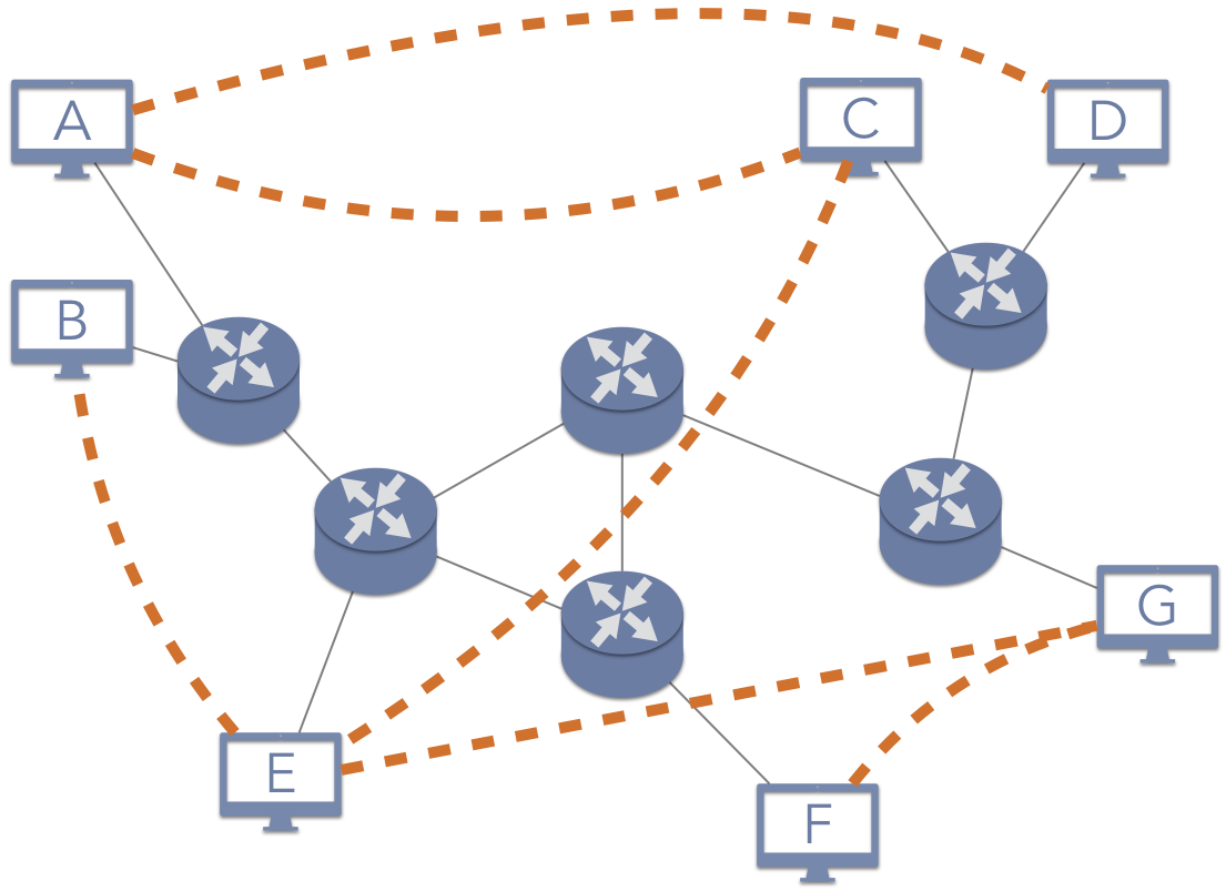
Figure 5.2.1: An overlay network, with links between nodes denoted by dashed links
A key concept within the domain of P2P applications is the notion of an overlay network, as illustrated in 5.2.1. In an overlay network, the participating nodes are processes running on different machines that are connected through the Internet. These nodes are arranged to have logical links—denoted by the dashed lines—that are independent of their underlying relationship across the Internet. In some cases, the overlay is designed specifically to hide these Internet relationships.
When nodes in the overlay network want to communicate, they establish socket links between their virtual neighbors. These neighbors may then contact their neighbors, and so on. For example, consider the structure shown in 5.2.1. Assume that node A would like to request data from node B. Based on the overlay, node A would contact node C; node C would forward the request to node E; and node E would forward the request to node B. To accomplish this, node A would open a socket link to node C, sending data to its access point and the other routers based on the solid line links. When C forwards the request to E, C would be sending data back along the same path of routers through the Internet. E would then send the data through a socket link to B. As such, this request from A to B would pass through the routers at least 11 times (five from A to C, four from C to E, and two from E to B), despite the fact that A and B are on the same local network. Depending on the particular application, the response from B might traverse the same path, particularly if the system is designed to provide privacy guarantees that hide information about users. On the other hand, the request that B receives might have A’s IP address information included, allowing B to create the socket link directly with A instead of sending the data back through the overlay paths.
5.2.1. Characteristics of Peer-to-Peer Networks
Given the assumption of an overlay network, there are two interdependent design decisions that must be made regarding the network’s operation. The first element is whether the overlay is structured or unstructured. Early public P2P networks, such as file sharing networks like Gnutella, employed an unstructured approach. When a user logged onto the system, their computer would contact an entry node that would then introduce this new node to the network. This type of network tends to experience a lot of churn, as nodes frequently enter the network for a short time then leave. Churn means that the network is constantly changing, so there is never enough time for a consistent, logical structure to emerge.
In contrast, more recent designs focus on structured P2P networks that impose a logical framework on the overlay network. For instance, the nodes might be assigned identifiers and arranged in a virtual circle. Node 1234 would be aware of nodes 1233 and 1235, but no other node. Other structures, such as a CDN, might define the logical structure to align with the physical proximity of the nodes; consequently, a service request could be directly to the node that would provide the shortest (and fastest) path to exchange data.
The second—and closely related—design decision for overlay networks is how to identify objects (such as files) in the network. In an unstructured network, a common technique is to use query flooding, which essentially involves asking as many nodes as possible. As an illustration, assume node E in 5.2.1 is requesting a file. E would send the request to its neighbors, B, C, and G. If any of those nodes had a copy of the file, they could provide it directly to E. If not, these nodes would forward the request to their neighbors, sending the request to nodes A and F. In query flooding, requests have a maximum number of hops—times that the request can be forwarded. Each time a node would forward the request, it decrements the hop count. Once the hop count reaches 0, the request is terminated and considered a failure.
Structured P2P networks provide more flexibility for identifying object locations. As these networks tend to have less churn (e.g., CDN companies tend to keep their cache servers constantly running with no downtime), the nodes are more likely to be in predictable locations. As such, these networks create an index that maps objects to the nodes that store them. The index might be local, so that a node only knows about the data stored at it and some neighbors. Systems with local indexes can use query flooding as in unstructured networks. They can also use an algorithmic approach to traverse the network in a predictable way; in Chapter 9, we will describe how the Chord P2P network accomplishes this task efficiently. Alternatively, the system may provide a centralized index, in which a single server maintains a global list of what data is stored at each node; any node requesting a file will first contact the index server to learn the location of the node to contact. Finally, the index may be distributed among several index servers that try to—but do not guarantee—maintain a consistent mapping of object locations. This is the approach of the Google file system, also described in Chapter 9.
In summary, P2P networks provide scalable solutions for many applications that would experience bad performance in client/server architectures. P2P networks operate by imposing an overlay network that defines the logical connections between nodes, while relying on the Internet to perform the actual data delivery. In some cases, routing in the overlay network leads to a significant amount of Internet traffic, as the nodes may not have enough information to direct their requests efficiently. In others, the overlay network is designed to minimize the impact on Internet traffic, and in some cases to even reduce it.
| [1] | DNS is sometimes described as a peer-to-peer architecture because of the distributed and replicated nature of the database. That is, each of the root and TLD name servers exchange data with each other as peers. However, DNS resolvers act solely as service requesters and do not provide a typical peer-to-peer service. As such, RFC 5694 characterizes DNS as client/server. |