1.5. State Models in UML
States are unique and meaningful configurations of the system. In some cases, a state may be defined by a particular combination of values assigned to certain variables. In others, several sets of possible values are grouped together within a single state. Transitions denote changes from one state to another. Transitions are triggered by events and can have effects that produce some visible behavior.
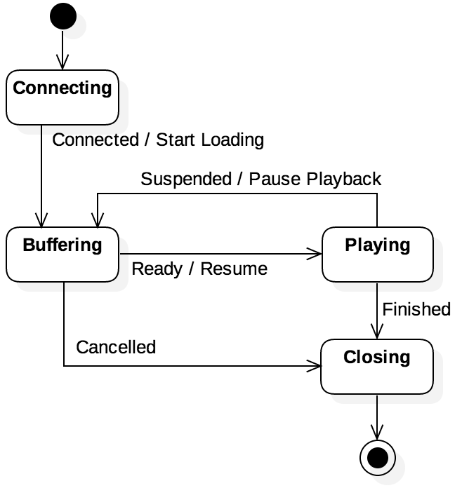
Figure 1.5.1: A UML state model for a streaming media player
UML state models are one way to visualize the behavior of a system from the
perspective of its states and transitions. Figure 1.5.1 shows an example of
a state model for a streaming media player. The player has four states: Connecting,
Buffering, Playing, and Closing. The arrows between states denote transitions, with the
following events defined: Connected, Ready, Suspended, Cancelled, and Finished.
These events correspond to both user input, as well as issues such as running out of buffered data
(the infamous buffering that frustrates users). Effects of transitions are denoted after the “/”
in the label, so the Connected event causes the effect Start Loading to retrieve the first
bytes to buffer.
The solid circle at the top indicates an initial state where the system starts, where the outlined circle in the bottom right denotes a final state. Some models may have more than one initial state or more than one final state. Observe that, in this case, there is no event labeled for the transitions from the initial state or into the final state. These are considered to be empty transitions and are not associated with any particular event.
State models are effective tools for illustrating the general flow between states and the overall
structure of the system. As is true of any model, state models convey some information while
omitting other details. Specifically, state models omit information relating to the sequence and the
timing of the states or the events. [1] For instance, in the case of the Closing state, the
system could remain in that state for 1 ms or 10 hours before proceeding to the final state; both
interpretations would be valid. Additionally, one execution of the system could completely avoid the
Playing state, while another execution switches between Playing and Buffering 100 times.
If more precise information is needed about the timing or the sequence of transitions, then other
models will need to be used.
1.5.1. State Space Explosion
Interpreting a well-defined state model should be intuitive; the states should be meaningfully different, and the transitions between them should be logical. However, constructing state models is not a straightforward process and requires a significant amount of practice to do well. One of the most intuitive challenges is how to deal with the state space explosion problem, which arises when the number of states in the model increase so dramatically that the model is no longer useful.

Example 1.5.1
One technique that can be used to evaluate a program for correctness is known as model
checking, which analyzes a formal specification of a state model. For instance, based on that
model, can we determine if the program will ever reach a state where a pointer variable is set to
NULL and the pointer is dereferenced? If so, we can examine the sequence of steps to get to
that state to debug the program.
To start this process, we need a model of the software program. Consider a naïve approach that
creates a unique state for every possible value of every possible variable. If the system contained
only a single 8-bit char (denoted ch1) the state model would consist of \(2^8 = 256\)
states. Add a second char (denoted ch2) and the model increases to \(2^{16} = 16,536\)
states. This fact arises from the observation that we must (without further knowledge of the
program) consider all 256 possible values of ch2 when ch1 is 0, then another 256 values
when ch1 is 1, and so on. If we convert both variables to the 32-bit int type and the model
has \(2^{64} = 1.84 * 10^{19}\) states, just to represent two variables.
This approach illustrates the dangers of the state space explosion problem. Because every additional bit of information doubles the number of possible states, state models can easily become unusably large. As such, it is critical to group configurations into meaningful states (such as positive and negative values for a key variable. However, determining what is meaningful is inherently application-specific and requires the judgment of someone with relevant expertise.
1.5.2. Implementing Finite State Machines
There are multiple ways to turn a state model into an executable finite state machine (FSM) [2] implementation. In fact, this is such a common practice that there are automated tools that will take a state model specification and generate executable code. The disadvantage with these types of tools is that the code is not necessarily readable. In this section, we will step through an example implementation that illustrates some of the key aspects of how these translations work.
Code Listing 1.1 shows the key declarations of a header file for a generic FSM. Event and state
types are declared as integer types, while the action type is declared as a function pointer that
takes a pointer to a FSM as an instance. The action type can be used for transition effects (as used
in this example), as well as for state entry or exit activities. Lines 15 – 21 declare our FSM
structure. Within the FSM, we will keep track of the current state, the number of events (used for
error checking), and a pointer to a transition function; this function will take in the current
state and event as arguments, then return the next state and the associated transition effect (if
any) to the caller. (Note that many implementations of FSM do not use this kind of struct, using
global variables for the current state and transition lookup tables. Our struct is meant to
encapsulate this in a way that we support multiple concurrent FSM instances if needed.)
1 2 3 4 5 6 7 8 9 10 11 12 13 14 15 16 17 18 19 20 21 22 23 24 | /* Code Listing 1.1:
Header file for a generic FSM handler
*/
/* States and events should just be integers */
typedef int state_t;
typedef int event_t;
/* Dummy struct for circular typedefs */
struct fsm;
/* Function pointer type declaration for effects */
typedef void (*action_t) (struct fsm *);
/* Generic FSM struct that could have other fields, as well */
typedef struct fsm {
state_t state; /* current state */
size_t nevents; /* number of events for this FSM */
/* pointer to the FSM's transition function */
state_t (*transition) (struct fsm *, event_t, action_t *);
} fsm_t;
/* Invoke an event handler for a given FSM */
void handle_event (fsm_t *fsm, event_t event);
|
Lastly, there is a single handle_event() function declared that will serve as the interface
between the FSM and the entity controlling it. Code Listing 1.2 shows the structure of this
function. The function starts by confirming that the event number is valid. If so,
handle_event() will call the FSM’s transition function to look up information about the
current event. This function will return -1 if there is no transition defined for that particular
state and event combination. I.e., events that invalid in the current state are ignored. Otherwise,
the effect (if any) will be executed on line 21 and the FSM’s state will be updated (line 22).
1 2 3 4 5 6 7 8 9 10 11 12 13 14 15 16 17 18 19 20 21 22 23 | /* Code Listing 1.2:
Body of handle_event() for a generic FSM handler
*/
void
handle_event (fsm_t *fsm, event_t event)
{
/* Confirm the event is valid for the given FSM */
if (event >= fsm->nevents)
return;
/* Use the FSM's lookup tables; if next is -1, the event is not
defined for the current state */
action_t effect = NULL;
state_t next = fsm->transition (fsm, event, &effect);
if (next == -1)
return;
/* Perform the effect (if defined) and change the state */
if (effect != NULL)
effect (fsm);
fsm->state = next;
}
|
Code Listing 1.1 and 1.2 provided a generic structure for any FSM. We now want to turn our
attention to the state model that we used in Figure 1.5.1 to model a simple media
player. The first step is to create a table form of the transitions between states. Table 1.1 shows
the table of the transitions for Figure 1.5.1. Each row of the table
corresponds to a possible current state in the model. Each column within that row represents the
next state based on a particular event, as well as any related transition effect. For instance, if
the Suspend event occurs while the FSM is in the Playing state, the next state would be
Buffering and the pause_play() effect would be; if the Finish event had occurred
instead, the next state would be Closing and there would be no effect. Any of the boxes in this
table that do not have entries indicate that there is no valid transition for that state and event combination.
Connect |
Suspend |
Ready |
Finish |
Cancel |
|
|---|---|---|---|---|---|
Connecting |
Buffering / start_load |
||||
Buffering |
Playing / resume |
Closing |
|||
Playing |
Buffering / pause_play |
Closing |
|||
Closing |
Table 1.1: Representing the transitions between states in Figure 1.5.1
Code Listing 1.3 documents how to turn Table 1.1 into executable code. To start, line 6 defines an
enum type for the specific states for this FSM instance, and line 7 creates a preprocessor constant
for the number of states. Recall from Code Listing 1.1 that states are, ultimately, integer types.
The advantage of using an enum is that it allows us to refer to states by names (e.g., CONN
for the Connecting state) instead of integers, which would be otherwise meaningless and likely
to cause errors. Line 8 defines a constant for the number of events based on similar enum for events
but defined elsewhere.
Lines 11 – 17 encode the transitions defined in Table 1.1. In the enum defined on line 6, the last
value (NST) is used to indicate no state, meaning that there is no transition defined. These
values in this two-dimensional array correspond to the blanks in the table. Lines 20 – 26 define a
similar lookup table, but for the transition effects. Since effects are actions that do something,
Code Listing 1.1 defined the action_t type as a function pointer; as a result, the empty values
in the table are NULL pointers.
1 2 3 4 5 6 7 8 9 10 11 12 13 14 15 16 17 18 19 20 21 22 23 24 25 26 | /* Code Listing 1.3:
Internal state and lookup table definitions for Figure 1.5.1
*/
/* Internal type definition of states */
typedef enum { CONN, BUFF, PLAY, CLOS, NST } ms_t;
#define NUM_STATES (NST+1)
#define NUM_EVENTS (NIL+1)
/* Lookup table for transitions; row=state, column=event */
static ms_t const _transition[NUM_STATES][NUM_EVENTS] = {
// Connect Suspend Ready Finish Cancel
{ BUFF, NST, NST, NST, NST }, // Connecting
{ NST, NST, PLAY, NST, CLOS }, // Buffering
{ NST, BUFF, NST, CLOS, NST }, // Playing
{ NST, NST, NST, NST, NST } // Closing
};
/* Lookup table for effects; row=state, column=event */
static action_t const _effect[NUM_STATES][NUM_EVENTS] = {
// Connect Suspend Ready Finish Cancel
{ start_load, NULL, NULL, NULL, NULL }, // Connecting
{ NULL, NULL, resume, NULL, NULL }, // Buffering
{ NULL, pause_play, NULL, NULL, NULL }, // Playing
{ NULL, NULL, NULL, NULL, NULL } // Closing
};
|
Note that Code Listing 1.3 declared both _transition (the transition table) and _effect (the
effects table) as static. This design choice helps to create a modular approach, as these tables
will not be accessed directly outside of this file. Code Listing 1.4 shows how these tables will be
accessed through the media_transition() function, also declared static in the same file.
Given the FSM’s current state, if the entry in the _transition table for the specified event is
not defined, return -1 to indicate no transition should be taken. Otherwise, set the effect
call-by-reference parameter to the appropriate function and return the next state. Note that, just
like the _transition and _effect tables, the media_transition() function cannot be
accessed outside the current file. The media_init() function provides the link. When a new
instance of this FSM is needed, the controller can use this function to get a new fsm_t, which
contains a pointer to the media_transition() function.
1 2 3 4 5 6 7 8 9 10 11 12 13 14 15 16 17 18 19 20 21 22 23 24 25 26 27 | /* Code Listing 1.4:
Connecting the specific FSM with the generic interface
*/
/* Given FSM instance and event, perform the table lookups */
static state_t
media_transition (fsm_t *fsm, event_t event, action_t *effect)
{
/* If the state/event combination is bad, return -1 */
if (fsm->state >= NST || event >= NIL || _transition[fsm->state][event] == NST)
return -1;
/* Look up the effect and transitions in the tables */
*effect = _effect[fsm->state][event];
return _transition[fsm->state][event];
}
/* Return an FSM that links to these internals */
fsm_t *
media_init (void)
{
fsm_t *fsm = calloc (1, sizeof (fsm_t));
fsm->nevents = NUM_EVENTS;
fsm->state = CONN;
fsm->transition = media_transition;
return fsm;
}
|
Finally, Code Listing 1.5 shows how a controlling program would create a FSM instance and send it
events. Since all of the information about the transitions and effects is encapsulated inside the
FSM struct, the controller just needs to focus on the logic of which event to send to the FSM.
Recall from Code Listing 1.2 that handle_event() passes the event through the FSM’s
fsm->transition function pointer to determine the state change and effect function. Since
handle_event() ignores invalid transitions, sending the wrong event (such as on line 7) cannot
cause an error in the FSM.
1 2 3 4 5 6 7 8 | /* Code Listing 1.5:
Creating an instance of the FSM and sending it events
*/
fsm_t *fsm = media_init ();
handle_event (fsm, Connect);
handle_event (fsm, Connect); /* no transition here ! */
handle_event (fsm, Ready);
|
| [1] | There are more advanced state models, known as timed automata, that do explicitly incorporate time within their representation. However, we will not be using those models in this book. |
| [2] | The term state model is often used synonymously with finite-state machine or finite-state automata. Here, we are using the terms separately just to distinguish between the non-executable model and its executable implementation. |