5.5. Internet Layer: IP
Transport-layer protocols, such as TCP and UDP, focus on the logical end-to-end communication between processes. Consequently, these protocols still avoid the fact that network sockets are exchanging data between different hosts. Instead, the transport layer still behaves very much like local forms of IPC. Internet layer protocols begin to remove this layer of abstraction. That is, the Internet layer extends the process-to-process structure of the transport layer with host-to-host communication.
The Internet layer consists of two interacting components. The data plane provides the overall structure of the network, assigning addresses to hosts. The Internet Protocol (IP) is the primary protocol for the data plane; IP identifies the logical location of a host within the Internet, both locally and across network boundaries. The control plane protocols define the routing paths that messages take through the network from a high level. These protocols include Open Shortest Path First (OSPF), Routing Information Protocol (RIP), and Border Gateway Protocol (BGP). We will provide a brief overview of the key features of the control plane protocols, but we will not be discussing the details of their operation.
5.5.1. IP Addresses and Subnets
In the previous chapter, we introduced the notion of an IP address as an identifier that can be used
to locate a host within the network. IP version 4 (IPv4), defined in RFC 791, specifies addresses as
32-bit values. For readability purposes, IPv4 addresses are typically written in dotted-decimal
form; for example, the address 0x01020304 would be more commonly written as 1.2.3.4. The 32-bit
length creates a serious problem for IPv4, as this size means there are only 4,294,967,296 possible
IPv4 addresses. While the exact number of devices connected to the Internet is impossible to
determine, all estimates are significantly higher than this limit of 4 billion; a more accurate
estimate would be on the order of 50 billion.
As the number of connected devices grew, one technique to compensate for the limits of IPv4 was to re-use addresses by dividing the Internet into multiple subnets, particularly private subnets. Private subnets are defined by a range of IP addresses that cannot be reached from hosts outside of that subnet. Subnets can be denoted using the Classless Inter-Domain Routing (CIDR) notation, in which a dotted-decimal value is appended with /n, where n is the length of the bit prefix for that subnet. For instance, 1.2.3.0/24 would denote the range of addresses from 1.2.3.0 up to 1.2.3.255, because the first 24 bits must match the subnet mask, which is the bitmask (255.255.255.0 in this case) that can be applied to any address in the subnet.
Readers who have set up a home wireless router may be familiar with the 192.168.0.0/16 subnet. This CIDR notation means the all devices that connect to the wireless router are assigned IP addresses that range from 192.168.0.0 to 192.168.255.255; the first 16 bits are designated to be identical for all devices. The IPv4 specification declares that 192.168.0.0/16 is a range of addresses that can only be used for a private subnet; similarly, 10.0.0.0/8 and 172.16.0.0/12 are also reserved. Choosing between the three ranges depends on the number of devices that will be connected. The 192.168.0.0/16 subnet allows 16 bits to vary, so the subnet can host $2^{16}$ (65,536) possible devices; this size is adequate for a home router. However, large organizations with thousands of workers may require more than that. Using 172.16.0.0/12 allows for up to $2^{20}$ (1,048,576) devices because 24 bits can vary; 10.0.0.0/8 supports up to $2^{24}$ (16,777,216) devices.
It may seem odd to allow the same IP address to be reused repeatedly. Specifically, if two devices share the same IP address, it may seem that there is no way to tell them apart. Figure 5.5.1 illustrates how this situation can be resolved. In this figure, Alice and Bob both have home networks connected to the same ISP. In both of their homes, Alice and Bob have wireless routers that assign addresses to devices that either connect wirelessly (such as a laptop) or via a cable (such as a desktop). Note that both networks have a device with the IP address 192.168.1.2. These IP addresses were assigned by the router using DHCP when the device joined the network. As these subnet ranges are private, Alice’s devices and Bob’s devices have no knowledge of each other. Alice’s phone (192.168.1.5) cannot communicate directly with Bob’s laptop at address 192.168.1.7. To Alice’s devices, Bob’s devices simply do not exist.
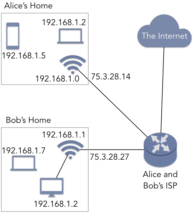
Figure 5.5.1: Two private subnets with common IPv4 internal addresses
When any device needs to access a resource outside the subnet (such as the Internet in general), the router acts as a gateway, using the IP address assigned by their ISP rather than the private address. The router contains a network address translation (NAT) service that performs IP masquerading. In this approach, the router has two IP addresses: 192.168.1.0 is used for communication with other devices in Alice’s home, while 75.3.28.14 is the IP address (assigned by the ISP) the router uses with the outside world. If any of Alice’s devices try to contact a website or to communicate with a P2P client on Bob’s network, Alice’s packets appear to be coming from 75.3.28.14—the IP external IP address of Alice’s router—rather than a 192.168.0.0/16 address. When data is sent back to Alice’s device, her router consults the NAT data structures to forward the packet to the correct device.
NAT and subnets provide one mechanism to deal with the limited number of possible IPv4 addresses, but it only provides a temporary solution. As a more long-term approach, IETF created IPv6, specified in RFC 2460, as the successor to IPv4. IPv6 increased the length of addresses from 32 bits to 128 bits. This increased the range of possible addresses from just over 4 billion to over $3 * 10^{38}$, an address space size that will not be exhausted in the foreseeable future. Given that private subnets can provide an element of security by keeping certain devices hidden from the greater Internet, IPv6 continues to support this feature, referred to as unique local addresses (ULAs). The CIDR address fd00::/8 defines the range of ULAs.
Note, though, that this CIDR address does not allow local networks to host up to $2^{120}$ devices.
Instead, addresses in this range must adhere to the structure shown in Table 5.9. The
first eight bits denote the value 0xfd, which constitutes the Prefix 1111110 and the
L bit 1, thereby designating a ULA. (Setting L to 0 is reserved for future use.) The
Global ID is a 40-bit pseudo-random assigned value that is intended to identify private networks
uniquely. Within that private network, the next 16 bits can be used to denote separate private
subnets. This structure then leaves 64 bits for individual devices, allowing up to $2^{64}$ ($1.8 *
10^{19}$) devices.
| 7 bits | 1 bit | 40 bits | 16 bits | 64 bits |
|---|---|---|---|---|
Prefix |
L |
Global ID |
Subnet ID |
Interface ID |
Table 5.9: Structure of a ULA in IPv6
5.5.2. IP Packet Formats
As with TCP and UDP, IP attaches a header to a transport-layer segment (the payload) for delivery. Table 5.10 shows the structure of an IPv4 packet. The source and destination address fields contain the 32-bit IPv4 address.
| 0-3 | 4-7 | 8-11 | 12-15 | 16-19 | 20-23 | 24-27 | 28-31 |
|---|---|---|---|---|---|---|---|
version |
length |
type of service |
total length |
||||
identification |
flags |
fragment offset |
|||||
TTL |
protocol |
header checksum |
|||||
source address |
|||||||
destination address |
|||||||
options |
|||||||
payload |
|||||||
Table 5.10: Structure of an IPv4 packet
The IPv4 header contains several fields that are not currently used in practice or to support
advanced features that go beyond the scope of this text. However, there are some fields that are
important to highlight. The 4-bit version field distinguishes between IPv4 and IPv6. The
protocol field specifies which transport-layer protocol (TCP or UDP) will be used to interpret
the segment header. As with TCP and UDP, IPv4 performs a checksum calculation to determine that the
header has not been corrupted. Note, however, that IP does not check that the payload arrives
intact. Recall that the terms packet and datagram are often treated synonymously; this lack of
integrity is related to that practice. Specifically, the term datagram generically refers to any
network data that is considered unreliable. Since IP provides no integrity check for the payload, it
is providing unreliable service and an IP packet satisfies the implication of the term datagram.
The TTL (time-to-live) field designates the maximum number of times that a packet can be
forwarded. Each time an IP packet is delivered to a router, either within a local network or within
the Internet as a whole, the TTL value is decremented. Once the counter reaches 0, the packet
will be destroyed by the router that currently holds it. This is one source of packet loss as
experienced by TCP. The TTL mechanism is vital for the overall success of the Internet, as it
prevents old packets from traversing the Internet forever, indefinitely consuming resources.

Example 5.5.1
To illustrate the structure of IPv4 address, recall the TCP message from Example 5.3.2. This message contained an HTTP GET request to a web server. The following example shows an IPv4 header structure that could be used with this particular message.
| Header | 4500 |
IPv4, length = 20 bytes (5 words) |
| Payload | See Example 5.3.2 | |
The length field (5) indicates the size of the IPv4 header in four-byte words (20 bytes total);
this field indicates whether or not optional headers are in use. The total length field
indicates the full size of the packet (including the IPv4 header, the TCP header, and the HTTP
GET request) is 96 bytes in size. The TTL indicates that the packet can be routed an
additional 8 hops. The protocol field (6) tells the receiving host how to interpret the
payload; in this case, the payload contains TCP data. Lastly, the source and destination addresses
are shown in both hex format on the left and their dotted-decimal translations.
For completeness, Table 5.11 shows the structure of an IPv6 packet. As expected, the
source and destination address fields have been increased from 32 to 128 bits. The TTL field has
been renamed as the hop limit, but the functionality of the field is the same. IPv4 contained a
field specifying the total length of the entire packet, whereas IPv6 specifies only the
payload length. This change arises because IPv6 headers are identical in length, containing no
optional fields. The other fields are used for features not discussed here.
| 0-3 | 4-7 | 8-11 | 12-15 | 16-19 | 20-23 | 24-27 | 28-31 | |
|---|---|---|---|---|---|---|---|---|
version |
traffic class |
flow label |
||||||
payload length |
next header |
hop limit |
||||||
source address (128 bits) |
||||||||
destination address (128 bits) |
||||||||
payload |
||||||||
Table 5.11: Structure of an IPv6 packet
5.5.3. Network Routing Protocols
While there are many routing protocols in contemporary use, three that are widespread are OSPF, RIP, and BGP. These protocols illustrate two ways to distinguish routing protocols. One way to distinguish them is based on the scope in which they operate. Recall that the Internet is not a single network; rather, it is a network of interconnected networks. Each of these networks can be considered an autonomous system (AS). An AS is a network of hosts (or subnetworks) that are centrally controlled by a single entity. For instance, a business, university, or home ISP may operate and maintain an independent AS. OSPF and RIP perform intra-AS routing, indicating that these protocols determine how packets are forwarded from one router to the next only within the context of that AS. For instance, if you are connected to a university network and try to access the home page of the university’s computer science department, your packets will only be forwarded within the AS via either OSPF or RIP; your packets will not be delivered to the other side of the world before coming back. On the other hand, BGP provides inter-AS routing; this technique is what allows you to access servers on a different AS, owned and operated by a different organization.
BGP, defined in RFC 4271, is a router-to-router protocol that uses TCP, with servers listening on
port 179. Specifically, BGP is executed on gateway routers that serve as
the entry and exits to an AS. Using BGP, the routers exchange information regarding particular
attributes of that AS. One attribute, the AS-PATH, defines the sequence of ASs that would be
traversed to a target network. For instance, an AS-PATH to a news website might go from your
university to your university’s ISP to the news organization. The NEXT-HOP attribute serves as
an identifier for the AS-PATH. When a gateway router receives a packet from its network, it uses
these attributes to determine the shortest total AS-PATH length to the destination.
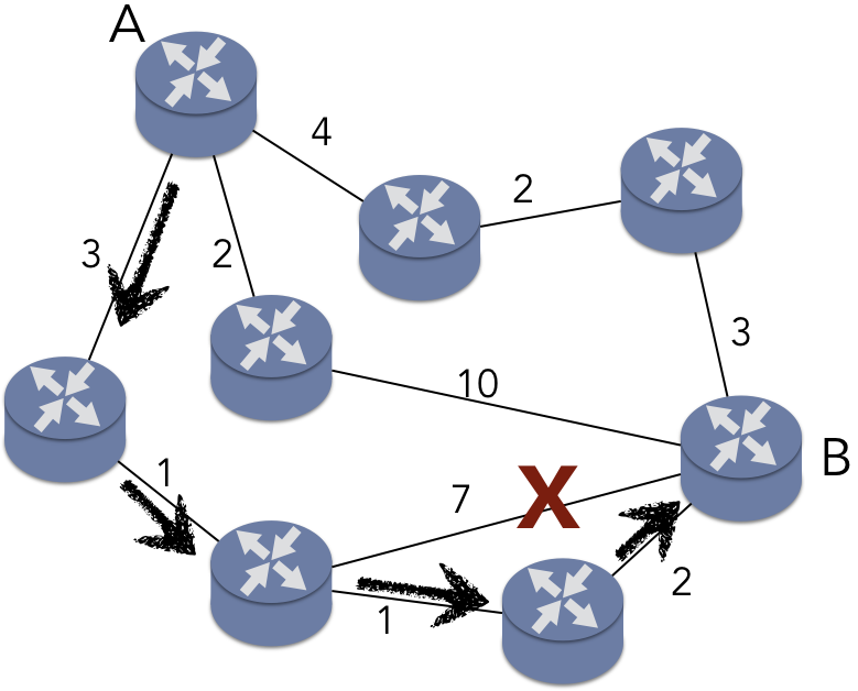
Figure 5.5.3: A network can be modeled as a weighted graph
The second key difference, as illustrated by OSPF and RIP, centers on how the shortest path is determined. OSPF, defined in RFCs 2328 and 5340, implements Dijkstra’s algorithm for finding the shortest path between nodes in a graph. This algorithm is a form of link-state routing, in which all of the routers within the AS maintain information about the network as a whole. To illustrate OSPF, consider Figure 5.5.3, which models a simple network as a weighted, undirected graph. In this scenario, router A is trying to route a packet to router B. The weights on the edges indicate a “cost” of using that network link, such as a time delay. The shortest path, denoted with the arrows, has a total cost of 7 ms. Note that the edge marked with an X would involve fewer hops between routers (only two intervening routers instead of three), but the total cost would be 11 ms, making that path more expensive. In OSPF, routers broadcast messages to ensure all routers have the same view of the network.
RIP, on the other hand, does not use Dijkstra’s algorithm. Instead, RIP employs dynamic programming to update each router’s local view of the network as things change, as described in RFC 2453. For instance, consider the router in the middle of Figure 5.5.3. This router has a link to B that currently costs 10 ms. Consider the effect of that link cost dropping to 1 ms. When this router becomes aware of the change, it updates its own internal information about the minimal cost of the path to B. However, the router also forwards this updated information to its neighbor A. A now discovers that it has a new shortest path to B: the cost of this path is 3 ms, rather than the 7 ms for the path shown in Figure 5.5.3. A would then inform its neighbors, but neither of A’s other neighbors benefit from this improved link. Consequently, the traversal of the information stops. This approach is known as distance vector routing.
When the distance vector routing terminates, the costs of the paths determined are identical to those established by OSPF. To be clear, the actual paths returned by the two protocols may be different, but the minimal cost will be identical. Using either OSPF or RIP, the total cost of the path from A to B will be the same.
This raises the question of why one approach would be preferred over the other. The two protocols have different features that offer advantages over each other. RIP imposes lower overhead on the network, as messages are exchanged point-to-point, rather than being broadcast. RIP also requires less space overhead, as the routers only need to maintain information about the cost of the path to each node, rather than a universal view of the entire network. However, RIP imposes a maximum hop limit, thus limiting the size of the network. OSPF also provides features related to multicasting and security.
In summary, the Internet layer extends the process-to-process communication of the transport layer with host-to-host communication. IPv4 and IPv6 specify the identifiers (IP addresses) that are used to locate a host within the logical structure of the network. IP addresses thus define the data plane of the Internet layer. The control plane consists of multiple routing protocols that determine the path between hosts, as defined by the links between routers. The RIP and OSPF routing protocols are used for intra-AS routing, determining the minimal cost path between hosts in a network that is under centralized control. BGP provides inter-AS routing, thus providing a mechanism for data to be routed between ASs that are independently owned and operated.