1.4. System Architectures
As stated previously, a model is a simplified representation of a system. Models are created to illustrate particular features of the system, while omitting other details that are not relevant to the current discussion. In other words, if we characterize a system implementation—with all details, variables, and states set to have particular values—as exhibiting a low level of abstraction, a model would possess a higher level. We can construct a model from an implementation by removing details, or we can construct an implementation by adding details to a model. However, both the model and the implementation are focused on a particular application. For instance, an automobile’s cruise control system would be an implementation, created from a model that illustrates which components determine the vehicle’s velocity, which entities calculate the changes to acceleration needed, and which ones adjust the rotation of the wheels. Both the model and the implementation are focused on the specific issue of acceleration in an automobile.
We can also approach the question of models from an even higher level of abstraction by examining the system’s architectural style. The architectural style describes the relationship between entities in the system and how those entities can communicate. Selecting a particular architecture has significant overall impact on the system’s performance and design style. Each approach has its advantages and disadvantages, and these must be considered for the intended use of the system.
1.4.1. Client/Server Architectures
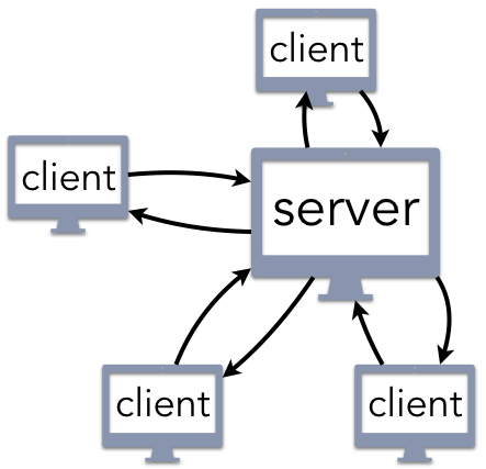
Figure 1.4.1: Multiple clients connect to a single server
Figure 1.4.1 shows the logical structure of the client/server architecture, a well-known and intuitive paradigm for building computer systems. The developer creates a centralized server that receives requests for service and responds accordingly. Web servers listen for requests created by a user’s web browser (the client) or an app running on a smartphone or tablet. Email servers allow you to send a message to someone else using a client application running within a web page or as part of a native email application. Network file servers can store large amounts of data, such as a collection of movies and music files; a streaming media client can then retrieve these files as indicated by the user.
When creating a client/server architecture, the first key question is to determine how the client
knows how to locate the server. The uniform resource identifier (URI)
approach is the most common, relying on standard Internet services to fill in the details. For
instance, the URI www.example.com/index.html indicates that there is a file named index.html
that can be accessed from the www.example.com web server. This answer is not entirely
satisfying, because it leaves unanswered how you are supposed to know where to find
www.example.com; the answer is you use a DNS client to contact a DNS server as a preliminary
step toward using your web client to contact a web server. The main idea in this approach is that
there is a single entity (the server) that provides a service to clients upon request.
Client/server architectures are common in user-focused applications, but they are also widely used in systems that do not provide visible services. As an example, several components of operating systems (OS) are designed according to a client/server architecture. For instance, the graphical user interface (GUI) is typically structured as a server that displays information in windows, manages the desktop, and directs keyboard or mouse input correctly; each application that is running acts as a client, sending requests to the GUI to update the visual display. Components that provide information about what applications are running, what the current time is, or whether a login request is allowed are all structured as servers. That is, anything that is typically described as an OS service exhibits a client/server architecture.
One advantage of the client/server architecture is the simplicity of handling updates. If a file is renamed, its contents modified, or changed in any other way, this change only needs to occur once. After the file or resource is updated on the server, the new version can be made immediately available. Relatedly, the centralized structure makes it easy to detect security breaches or data corruptions. If a user reports a broken link or some other bad result, the problem only needs to be fixed in one location.
From a communication perspective, client/server architectures rely on communication protocols, standards that specify precisely how to request a service and interpret the response. Protocols are necessary, because there are no pre-defined assumptions regarding who can be a client. Returning to the previous examples from above, a web server defaults to responding to requests from any web browser connected to the Internet. The email server that you are using will accept incoming messages from anyone, including a long-lost friend attempting to reconnect or a criminal enterprise sending you spam with a virus attached. So long as the client and server adhere to the communication protocol, messages can be delivered to and from the server. Granted, after the server receives the message, it may use a spam filter or other security mechanism to discard it without your knowledge; however, the message was still delivered to the server itself.
Client/server architectures have a key feature that is both an advantage and disadvantage: centralization. Maintaining a single server makes it easy to process changes efficiently and provide consistent service. The downside of this is that the system has a single point of failure. If the web server crashes, then the entire service is down. The single access point also creates a bottleneck when many clients try to request service at the same time. As an analogy, imagine going to a restaurant that only has one table. That is not a problem for most of the day when there are few (if any) customers arriving; however, the restaurant would quickly go out of business since it could not serve enough customers during the busy (and profitable) meal-time rushes. One way for client/server architectures to solve this problem is to use replication. Instead of using only one server, a few servers coordinate the work very closely, providing backup to each other. This would be analogous to adding more tables to the restaurant.
1.4.2. Peer-to-peer (P2P) Architectures
This idea of replication can be extended even further to the notion of peer-to-peer (P2P) architectures. Figure 1.4.2 illustrates the logical structure of a P2P architecture. P2P architectures retain many of the key features of traditional client/server architectures, with the exception that every (or most) participating entities take turns acting as both clients and servers. Any node in the architecture can communicate with any other, requesting or providing service as needed.
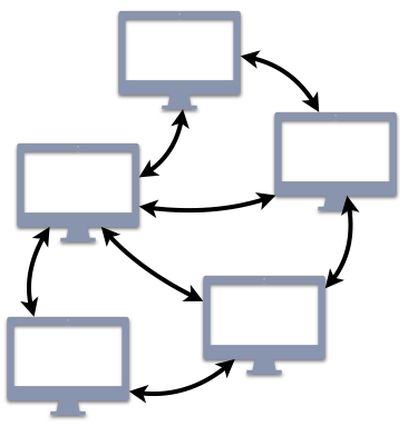
Figure 1.4.2: All P2P nodes are clients and servers
For many readers, P2P architectures are probably associated with file-sharing services, such as
BitTorrent. In that service, you may use your client to download a file provided by another user; in
return, while you are connected to the network, other users can also download that same file (or
pieces of it) from your client. P2P architectures go beyond just this single application, though.
Another common example of a P2P architecture is DNS, the service that translates human-readable
domain names (www.example.com) into a numeric IP address. (We will cover many of the details of
DNS in Chapter 4.) Although your web browser interacts with DNS in a traditional client/server
approach, DNS itself consists of a world-wide P2P network of systems that exchange information to
support these translations.
Overall, P2P architectures extend the client/server paradigm with the benefit that they scale well by maintaining good (or even better) service as the number of users increases. For instance, in a system like DNS with P2P nodes distributed world-wide, your request can be routed to the server that is physically closest to you. Consequently, your request would be handled more efficiently than if the message had to be transmitted to the other side of the world.
The tradeoff for these scaling benefits is more difficulty in both administration and security. For instance, if one of the nodes is corrupted so that it serves spam or other malware, system administrators may struggle to identify which particular node is causing the problem. Another problem that arises from this tradeoff is that updates are not guaranteed to be immediately accessible. When a file is updated on one node, that change needs to be communicated to all of the other nodes, which takes time. While this change is propagating, that file may be designated as not available or only the old version can be accessed. The choice between traditional client/server and P2P architectures must account for all of these factors.
1.4.3. Layered Architectures
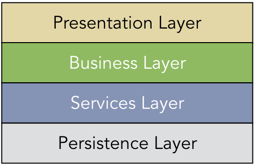
Figure 1.4.3: Common layers for an information system application
In a layered architecture, the system structure is arranged in a hierarchical order of modular components. Figure 1.4.3 shows a common layered architecture that is used in building information systems. In this design, the user interacts with the Presentation Layer, which is responsible for the user interface and other graphical components. This layer can interact only with a Business Layer that encodes domain-specific business logic, such as adding new employees to a human resources database. The Business Layer may interact with a Services Layer that defines common processes that are used for a variety of application. User authentication and security mechanisms would commonly be implemented as such a service. At the bottom level, the Persistence Layer contains the database and other mechanisms for storing data.
Client/server and P2P architectures support bidirectional communication between any entity that adheres to the specified protocol. In contrast, a layered architecture imposes a strict ordering to the allowable communication. Each layer is designed to interact only with the layer immediately above and the layer immediately below. For instance, in Figure 1.4.3, the Presentation Layer should never interact directly with the Services or Persistence Layers. Instead, all data that the Presentation Layer receives for long-term storage would need to be passed to the Business Layer, which would forward the requests on to the lower layers.
One significant advantage of the layered architecture approach is that the layers can be independently modified and replaced with new components. Switching the Persistence Layer to use a different kind of database would not affect any of the other layers, assuming the interfaces are preserved and the layers are cleanly defined. Furthermore, new layers could be added as the application evolves, allowing for an extensible and modular approach.
On the other hand, the layers of many systems are hard to delineate cleanly in a single hierarchical ordering. Some systems have circular dependencies that cannot be easily resolved, while others have layers that are not truly independent. For instance, consider the relationship between a file system and the physical storage device driver in an OS. In theory, file systems could break files into pieces of any size; in practice, all file systems structure data in chunks that are multiples of 512 B, because that is the standard size imposed by the cables used with hard drives. Consequently, it does not seem efficient to ignore this reality when defining the file system layer. Similarly, there may be good reason to allow messages to bypass layers. For instance, the Business Layer may need to store a significant amount of temporary data until an approval (implemented in the Services Layer) is granted; thus, the system could benefit from granting the Business Layer direct access to the Persistence Layer.
A related problem with layered architectures is that there tends to be unnecessary redundancy and inefficient mechanisms. As an example of the former, consider the layers of the Internet protocol stack, which we will discuss in Chapter 5. The layers of this stack use the terms segment, packet, datagram, and frame to refer to a structured message that contains a header and a piece of data. Granted, there are subtle nuances between some of them, but the concept is very similar. Additionally, all of these layers include error checking mechanisms to ensure that none of the bits of the message have been corrupted; when a message arrives, multiple layers all perform the same calculation to check the message’s validity.
1.4.4. Pipe-and-filter Architectures
In contrast to the previous architectures, pipe-and-filter architectures impose a unidirectional ordering on communication between system components. The data processing begins at the source of the input and proceeds through a series of stages. The output of each stage becomes the input of the next, with the intention that each stage transforms the data in some way. The final result is referred to as the sink, which denotes the output. Readers who have some familiarity with working on the UNIX or Linux command line are likely to have encountered a pipe-and-filter architecture, created by the following sample command line:
$ sort foo.txt | grep -i error | head -n 10 > out.txt
In this sequence of commands, the contents of the file foo.txt are sorted and sent to the grep
utility, which performs text matching (finding “error” in a case insensitive manner). The lines that
contain “error” are then sent to the head command that grabs only the first 10 lines of output,
writing the results in a new file called out.txt. Figure 1.4.4
illustrates this sequence as a pipe-and-filter architecture.
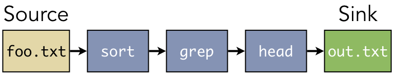
Figure 1.4.4: The pipe-and-filter system constructed from chaining command-line utilities
In this example, the system was constructed dynamically by linking these command-line utilities together. That is one way for creating a pipe-and-filter architecture. If there are several independent modules that share a common interface (a stream of bytes as input and output), then a pipe-and-filter system can be constructed from any composition of these components. Other pipe-and-filter systems are not dynamic, and the sequence of stages cannot be re-ordered.
One example of such a pipe-and-filter system is a programming language compiler. The source code is
passed through a lexical analysis stage to recognize keywords (e.g., “if” and “while”) and other
language components. These tokens are passed to syntax analysis to check for errors, such as
forgotten semicolons or other invalid code. Next, the semantic analysis stage checks for type
mismatches (e.g., initializing an int variable with "foo"). These stages, which make up the
front end of the compiler, lead to the generation of intermediate representation. The processing
continues with additional stages to optimize the code and generate the machine-language executable.
One significant disadvantage of a pipe-and-filter architecture is the unidirectional structure does not allow for error recovery. For instance, if you chain together 10 command-line utilities and the third one wipes out all of the data being processed, the later stages cannot recover the eliminated data. Furthermore, it may not be immediately evident which stage was the cause of the lost data. Despite this drawback, however, pipe-and-filter architectures are very good for serial data processing.
1.4.5. Event-driven Architectures
The last major style that we will consider here is the event-driven architecture. An event refers to a meaningful change in the state of the system. For instance, in a GUI, keyboard presses and mouse clicks are instances of events. When either of these occur, the user is indicating a desire for the system to respond to this request in some way. Figure 1.4.5 illustrates the logical structure of an event-driven system. An event generator is any input device that can trigger the creation of an event. A keyboard and mouse are event generators in a GUI; the server that a mobile app uses to connect to other users would also be an event generator. The events are sent through an event channel, such as an HTTP connection or a wire, where they are received by an event processing component. This component detects the type of event that was triggered and invokes the corresponding event handler to respond accordingly.
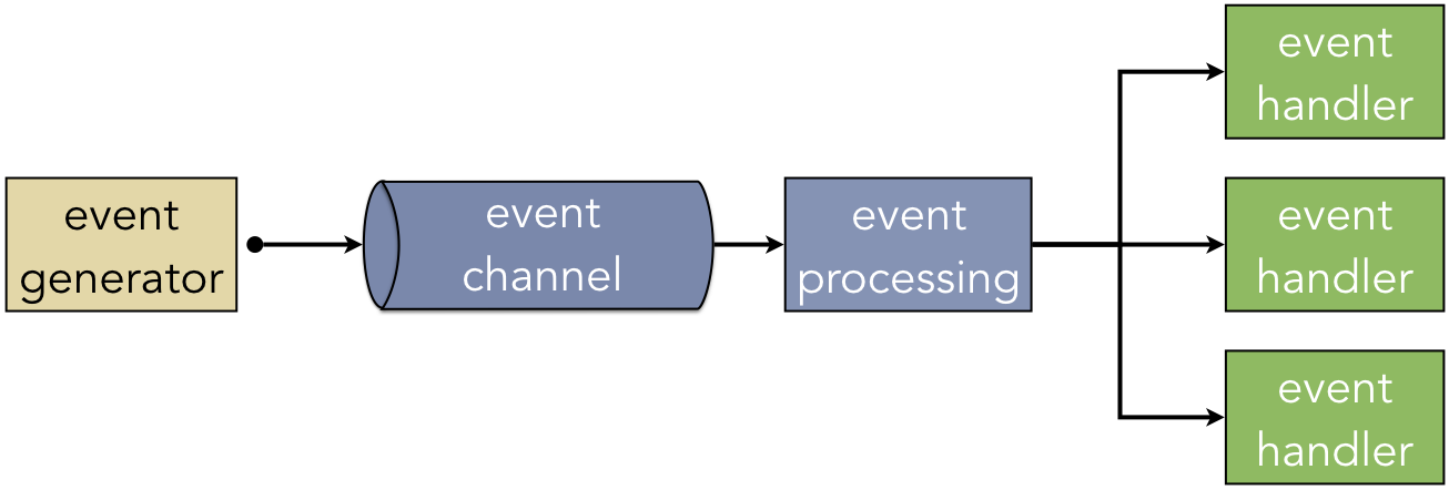
Figure 1.4.5: The logical structure of an event-driven architecture
Event-driven architectures are effective designs for reactive systems. By differentiating the event channel, event processing, and event handlers as distinct components, this approach creates a robust and extensible framework. To support a new type of event, the developer creates the event handler and makes the event processing layer aware of it. Similarly, the channel can be modified and upgraded without affecting the event handler operations.
One drawback of the event-driven architecture is how it complicates the timing of access to shared resources. Some event handlers are designed to have higher priority than others, and some event handlers may take a while to complete. Consequently, if a low-priority event handler is currently using a shared resource when a high-priority event arrives, the correct response is not immediately clear. The low-priority handler may need to finish its work to keep the system in a stable, consistent state because it has made some changes that cannot be undone. However, the high-priority handler is, by definition, supposed to run first. As such, correct handling of events can be complicated.
1.4.6. Hybrid Architectures
In practice, computer systems rarely fit into exactly one architectural style. Many systems are best described as hybrid architectures that can be viewed from different perspectives depending on the context. This hybrid structure is particularly common when systems are composed of subsystems that operate independently. Some subsystems are more naturally aligned with one architecture than another, implying that there is no single architecture for the whole system.
One example of this is an OS kernel, which is the central system that provides applications with managed access to the hardware. From one perspective, the kernel is an event-driven architecture, as it consists of a collection of interrupt handlers that respond to signals (interrupts) from the hardware that something meaningful has occurred. Those events can include plugging in a USB drive, receiving data from a network card, detecting keyboard presses, being alerted to low battery power, and so on. From a different perspective, the kernel is also a client/server architecture. Applications that are running use the system call interface to request access to a shared resource. These requests include sending and receiving pieces of data across the network, opening and closing files, sending audio data to the speakers, and so on. Furthermore, some aspects of the kernel are designed as layered architectures. File systems, for example, are often structured in layers that convert generic file operations (reading, writing) into operations that are specific to the particular organization of a specific device; that is, the device may use file systems such as FAT32, HFS+, ext4, or NTFS, and the kernel maps the generic operations as needed. Thus, there are systems, such as OS kernels, that can exhibit the features of more than one architecture based on which aspect of the system is being considered.