- Forward


UML Deployment Diagrams
An Introduction


Prof. David Bernstein
James Madison University

Computer Science Department
bernstdh@jmu.edu

Print

Introduction
Back SMYC Forward
  • Purpose of Deployment Diagrams:
    • To model a physical architecture
  • Elements:
    • Artifacts - a physical manifestation of a non-software element of a software system (e.g., files)
    • Components - a software element of a software system (e.g., an application)
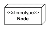
    • Nodes - computational resources (i.e., a physical device or an execution environment such as a virtual machine)
Visual Representation of Artifacts and Components
Back SMYC Forward
  • Artifacts:
    • deployment-artifact
  • Components:
    • deployment-component
Visual Representation of Nodes
Back SMYC Forward
  • In General:
    • deployment-node
  • Common Stereotypes:
    • <<device>>
    • <<execution environment>>
    • A description of the computational resource
Visual Representation of Relationships
Back SMYC Forward
  • Communication Paths:
    • A solid line between elements
  • Static Deployment:
    • An artifact/component is placed in a node
  • Dynamic Deployment:
    • A dependency arrow (a dashed arrow with the stereotype <<deploy>>) connects the artifact/component to the node
An Example
Back SMYC Forward
deployment-diagram_quiz-example
There's Always More to Learn
Back -